Building a TrakSim Map
Overview
This document describes how to use the BuildMap
function to create your own track maps for TrakSim.
TrakSim is designed around a full-size "park"
256x200 (park meters) encoded as a grid of 2m squares -- in the default
1:8 scale, the grid squares are actually 25cm = 10" -- where each grid
square may contain a straight line segment of track edge, or else be wholly
track or entirely off-track, or otherwise undefined (outside the park).
This document describes the
BuildMap function and its various
operators
(in a text file) for defining the properties of the park used by TrakSim.
You need to create a track descriptor text file
describing the properties of the "park" that the simulated car will drive
around, and if you have any superstructure, any objects that rise above
the ground level (other than interior walls), you need to create an image
file containing RGB images of each type of artifact
you want TrakSim to display, in each perspective you want it to be seen
from, and make the pixel array from that file available to the
BuildMap
function. One of the TrakSim APIs is a ReadTiff32Image method
to read in an uncompressed RGB Tiff32 file, which
you can use for that purpose if your image file is compatible. Part of
the track descriptor text file is used to define the image locations and
sizes and placement on the track map, which is described in the section
on Artifact Specification. The
BuildMap
function returns an array, which if you write it to a file named "TrackImg.indx"
then TrakSim will read it as its default track.
Each track descriptor in the text file begins
with a single line specifying five Global Park Properties.
This is followed by any number of lines describing individual Track Details,
including the location and orientation of artifacts. The details section
ends with a period in the first position of its line, optionally followed
by image specifications for artifacts as described in the section on Artifact
Specification. The first descriptor (or
the descriptor named in the first line) is the one that is used. If there
is a problem reading a valid descriptor from the file, then the default
track is used.
Included in this distribution is a track descriptor
file "TrackImg.txt" containing several example track descriptors.
Many
of the tracks in that file have image components, which are included in
the accompanying "TrackImg.tiff" file. You can read about the
placement and sizing of those image fragments in the "Image
File Coordinates" page of this website.
Most of the examples in this document come from
the first descriptor in that file, named "Figure-8".
Following
that descriptor are three or more tracks designed to resemble the actual
F-1/10th race tracks to date, which are described in the F1/10
example tracks page of this website. Delete
the first descriptor (or move it elsewhere in the file) in order to use
the second.
Later in the track descriptor file is the descriptor
"Brussels" which approximates the track we laid
out on the floor in the Brussels hall exhibit area. I prepared what is
now "BruxEst" as a guess before we went, but left it in the file for pedagogical
purposes. I also prepared the "PSU TestOval" as a modest
first cut at what the participants in the third annual NWAPW
might need for testing their work, but the reflections on the slick concrete
floor proved insurmountable; it also is preserved (later in the file) for
pedagogical purposes. I added another track "PSU Stairwell"
resembling the actual demonstration run on 2018 August 10.
New This Release
You can put an index of all the quoted track descriptor
names at the front of the file, and the first line names the descriptor
that is used. The name must be exactly as it is in the first line of its
descriptor for this to work. Previously you had to move the entire descriptor
to the front, now you need only put its name at the front of the file.
I added image wall specifications to more closely
model the race tracks used by the F1/10 organization. Examples are in the
"F1/10" example tracks, also in this release.
You can also set ceiling properties and a different coefficient of friction
for each separate track descriptor file.
Prior Release
I rewrote the track curve macros so that you can
get credible curves of any radius up to 32 park meters (16 grid units =
4m actual), and so that you can start or terminate curves other than on
compass points. This simplifies the task of writing track descriptors,
and the Track Operators section of this document now
reflects that.
I originally planned to allow background scenery
like trees and spectators and buildings, but ran out of time. Now we need
this kind of boundary artifacts to simulate the F1/10 race tracks, which
so far do not have edge lines, but depend on the cars being able to see
the barrier walls. We need carefully placed boundary walls so your software
can calculate the distance based on wall height.
Previously I added some specifier codes for
pebbling
and for luminance control.
Artifact descriptors can be tagged with a "!"
to signify that they trip the new proximity detector feature.
Global Park Properties
The first line of the track descriptor file must
begin with five numbers, which may be either decimal or (Java) hexadecimal.
Here is the first line from the "Figure-8" track descriptor:
0x700070 0x96931963 0x38002C 90 13,8
"Figure-8" -- 2018 August 20
The first number 0x700070 defines
the logical (full-size)
"park" dimensions in meters (yards), in
this case 112x112. If you are running 1:8 scale model cars (some people
call them 1/10th scale), then the actual floor size would be 14x14 (meters)
or 45 feet square. The upper (first) 16 bits is the north-south dimension,
and the lower 16 bits is the east-west dimension.
The second number 0x96931963
defines the track and floor or ground coloration. Like the park
dimensions, it is divided into two 16-bit parts, actually 15-bit parts,
with the two upper bits in each half having other significance. The low
half of the number specifies an RGB color for the
track, and the upper half specifies the color of non-track (but in-park)
ground. In our example, the track is brown (R=9, G=6, B=3) and the non-track
is green (R=6, G=9, B=3). The next three bits in each half determine the
degree of darkening for the checkerboard odd squares (1: -3). A pure black&while
checkerboard would be represented by 0x5FFF5FFF. Of
course the darkening factor has no effect if checkerboard is disabled.
The sign bit on the second number signifies that
this is an indoor track, and the background is a slightly darker wall (see
Walls
below). If positive, the backdrop is a flat green below the horizon and
sky blue above. The middle bit enables track pebbling, see PebbleSize
and PebContrast.
The third number 0x38002C defines the
position of the car in park meters at startup, in this example 56 meters
south of the top edge of the map (in 1:8 scale, 7m from the north wall
of the 14x14m room) and 44 meters east of the left edge.
The fourth number is the direction the car is
initially pointing at startup, in integer degrees clockwise from north,
in this example facing due east.
The fifth number defines the width of the white
line on the track edges in integer park centimeters, in this case 13cm
= 5" -- which in a 1:8 scale track would be about 3/4" wide tape on the
floor. If you omit this number then the default specified in the WhiteLnWi
constant is used, but an explicit zero-width line does not draw it on the
screen.
If you attach (with no spaces) a sixth number
to the edge line width, it specifies the contrast to be used in pebbling
the track, which is a single digit from 1 (minimal contrast) to 9 (maximum).
If this number is zero or omitted, the default PebContrast
is used. If you specify your own pebble values,
they override the contrast control.
The remainder of the first line is ignored and
can be used for comments or a title or whatever. In this example (and throughout
the distribution file) it's a descriptor name and revision date for each
descriptor.
Track Details
The main body of the track descriptor file consists
of a sequence of track operators, tagged lines where each significant line
begins with a capital letter or other character identifying what operation
this line specifies. Lines that begin in any other way are ignored and
can be used for comments. The end of the track details section is signified
by a period in the first position of its line. These tags are defined in
this release:
@ -- Time &
Position for an animated artifact
A -- Advance track
edge some number of grid (2m) units
B -- Bucket Fill
C -- Curve backround
image wall to left
D -- Curve backround
image wall to right
E -- Advance track edge Eastward
(usually generated by macro)
F -- Rectangular area Fill
G -- BackGround image
wall
H -- Horizontal
(eastward) plain wall
I -- Initialize
as no prior
J -- Macro to build moving
artifact sequence
K -- (internal use only)
L -- Macro to curve track edge to the
Left
M -- One-cell Manual
wall segment
N -- Advance track edge Northward
(usually generated by macro)
O -- Object specification
(usually generated by macro)
P -- Pilaster (vertical Post,
otherwise like a wall)
Q -- Convert
track to non-track
R -- Macro to curve track edge to the
Right
S -- Advance track edge Southward
(usually generated by macro)
T -- Start Timing
sequence
U -- Painted
Image
V -- Vertical (southward)
plain wall
W -- Advance track edge Westward
(usually generated by macro)
X -- Erase overstrike
prevention history
Y -- Macro to build static
artifact
< -- Set BackWall
color
= -- Rectangle of uniform
luminance
> -- Luminance point
source
[ -- Pebble specification
] -- White Line Color
` -- Set Coefficient
of Friction
8 -- Set Floor tile specification
9 -- Set Ceiling height
. -- End of track operators
Some of these specifications refer to image
fragments in the "TrackImg.tiff" file. Placement and size information
for the distributed version are tabulated in the "Image
File Coordinates" page of this website.
Most of the coordinate numbers in this section
specify a position on the park map, which is partitioned off in 2-meter
units, a maximum of 256 meters (128 grid units) wide (west to east) and
200 meters (100 grid units) high (north to south), so you should not be
using positions greater than 99(V) or 127(H). Luminance coordinates are
in park meters (double the corresponding grid coordinates). Most operators
also reject position 0 either way. When a position is given, the first
number after the tag is the vertical (southward from the north edge) coordinate
and the next number is the horizontal coordinate (eastward from the west
edge). Sometimes (as noted) fractional positions can be used, and resolve
to 25cm (park, eighths of a grid unit =3cm on the floor in a 1:8 scale
simulation).
The track is defined by its right edge, that is,
you should outline the track by tracing its edge counter-clockwise all
the way around. In the most common case of (circular or oval) tracks that
loop back on themselves with islands of non-track surrounded by one or
more track loops, you need to define the outside edge counter-clockwise
around the outside, and then re-initialize the chaining and traverse each
interior island clockwise, so that your advance always leaves track on
the left, non-track on the right.
If you use one of the compass-named advance operators
(N,S,E,W), they always depend on a previous advance
to have ended somewhere, then specify where the next segment ends. The
first time you use one of these, there is no previous end, so the given
coordinate does not advance anywhere, but it does define a new starting
point and direction. Using the 'A'
Advance
operator continues in whichever of the four compass directions you left
off for that many grid units. Using a Left or Right
turn operator turns the track 90 degrees in the specified direction and
sets a new current compass direction, unless the curve is shortened below
45o.
The Advance and turn macro operators always assume
compass directions and a track edge that passes through the middle of grid
cells, but you are not restricted to those four directions. If you use
one of the compass directions, you specify an ending point, which needs
to be more or less in the specified direction, but may angle off as much
as 45 degrees to the left or right. This is in fact how the turn macro
operators make curves: they lay out a sequence of short straight segments
angling more and more in the desired direction. You can make your own diagonals
and partial curves to connect with the rest of the track constructed with
macros, or you can ignore the macros entirely and use the compass operators
directly, although it is significantly more work to get the track to look
reasonable.
Besides the track operators,
there are separate operators for specifying areas and walls,
and for specifying
artifacts that rise above the
floor of the track, which are grouped for discussion separately. These
operators are now discussed in this somewhat logical order.
Area & Wall Operators
F -- Rectangular
area Fill -- F nn ww ss ee cc
Four rectangular coordinates are specified,
respectively the North, West, South, and East edges of the rectangle to
be filled with cc either non-track (0) or track (1) or
else to erase to virgin non-park (-1). Normally you designate the park
area with a rectangular fill, but you can erase holes into that space.
You can also use the Fill operator to fill in small holes within the track.
B -- Bucket
Fill -- B vv hh cc
You can fill an arbitrary region using
the tool that works like the paint bucket in paint programs. Specify the
map grid coordinates vv,hh where the drop
starts, and it will fill all contiguous (left/right/up/down, but not diagonal)
map cells touching it. You can fill the contiguous cells with cc
track (1) or non-track (0). Only previously unfilled cells and cells containing
the opposite color will be filled; cells already filled with the same color,
as well as walls and track edges stop the flow of the fill. If you want
to build a non-rectangular park area, you can use the track edge operators
to surround the irregular boundaries, Bucket fill the enclosed region with
track, then use the Convert to non-track (Q) operator to
make that area into park.
Artifacts
H -- Horizontal
(eastward) plain wall -- H vv hh ee cc
V -- Vertical
(southward) plain wall -- V vv hh ee cc
P -- Pilaster
(vertical Post) -- P vv hh cc*nn
You can define walls that are a single
grid thick (that would be two meters thick at full scale, or for example,
25cm=10" thick at 1:8 scale). Plain walls
are generally visible from both sides -- unless they are very close to
the park edge, but then you couldn't drive the car behind to see, could
you?. If you specify the walls after you lay out your floor, their grid
cells will show in your map views; otherwise there will only be thin lines
along the walls' front edges. The ee
parameter is the ending horizontal grid position for H (west-east)
walls, or vertical for V (north-south) walls; it should be greater
than the corresponding start. If the Indoor Map (sign bit) flag is set
in the floor coloration word of the first line, and if you did not explicitly
set out exterior walls using wall operators, then one of those colors.
Four colors are defined in the class
DriverCons
(see "Scenery Colors") for wall-like
objects. Horizontal and vertical walls can be CreamWall (cc=1),
DarkWall
(cc=2), BackWall (cc=3) or PilasterCo
(cc=4). Posts (pilasters)
are defined in their own color,
PilasterCo which is initially
set to a medium gray, unless you redefine
it or include the optional cc parameter. Posts are
normally one grid square (default *nn=1, 2m), but you can
specify larger sizes.
TrakSim orders the walls by their sequence in
the file, and in case of multiple walls showing up over the same pixel
row on the screen, the later walls are usually presumed to be in front.
You should therefore arrange your specifications of multiple wall layers
with that in mind. This affects both plain walls and image walls (next).
C -- Curve backround image wall
to left --
C vv hh dd rr ee-ss tt ww xx^yy pp nn*
D -- Curve backround image wall
to right --
D vv hh dd rr ee-ss tt ww xx^yy pp nn*
G -- BackGround image wall --
G
vv hh dd ff+aa tt ww xx^yy pp$u.u nn*
--
or -- G vv hh qq/zz ff+aa tt ww xx^yy pp 0!
You can specify walls using images in
the "TrackImg.tiff" file. The vv and hh
coordinates specify (in 2m grid units) the map coordinates (called the
anchor) of the left end of the image, which is tt pixels
tall and ww pixels wide, beginning in the file at pixel
row yy, column
xx (specified in a single
word) The image resolution pp is in pixels per meter (in
park meters), which should be at least 4 and not more than 256. If you
include an optional length specification nn in park meters,
or you have an explicit end cell qq/zz), you can force-fit
exactly (!) or repeat (*) the image for
longer runs, or else to cut it shorter than the image without calculating
exactly how many pixels that would be. You can also optionally designate
an alternate horizontal (possibly fractional) scale factor ($u.u)
to get images to line up properly. You cannot use a wall image taller than
1K pixels.
The wall normally is angled (from north) some
number of degrees dd clockwise from north, where 0 means that the
wall faces east, with pixels to the right of the anchor north of the origin
vv,hh.
The actual angle of the wall face may differ by a few degrees from the
angle you specify, because the endpoints need to be on the corners of whole
grid squares. Alternatively, you can specify an end cell qq/zz
different from the anchor (and not a length), and the angle will be computed
for you.
TrakSim tries to link up wall segments that start
at or near the end of a previous segment. You should understand that the
face of the wall is determined by the front left corner of the anchor grid
cell to the front right corner of the end cell, and TrakSim tries to adjust
that right corner so it matches the front left corner (anchor) of the next
segment face, so that there are no gaps in the wall at corners or bends.
The "front" of the wall is the long side to your right when you sight along
the wall from its anchor toward the end. Walls specified at exactly 45
degrees are presumed to be facing north or south (rather than east or west).
The wall is only visible from its front side but
you can overlay a wall facing the other way. Normally you would list several
wall specifications with different images and view angles ff
(where 90 is 90o square-on), so
that if viewed from outside the view range +aa (where +60
means 30o to each side of the view angle,
a total range of 60o) for any one of them,
this wall specification is disregarded (and should be followed immediately
by one or more additional wall specifications with the same left-end coordinates);
if none of the specifications are visible, the wall is not shown. Use a
single "0" for ff (and no +aa)
for a wall that is visible as the same image from all angles (except behind
it). You can use these different images and angles of the same wall for
oblique or end-on views of the end or corner of the wall. Other than these
end-caps, you should avoid specifying walls that branch off in different
directions from the same anchor cell, because the linking may not work
properly.
For your convenience, the two curved wall macros
work more or less like the curved track macros with
a specified radius rr (in 2-meter grid units), so you can
place an image wall directly over the track edge with reasonable expectation
that they match. Like the track curves, the wall curves start and stop
on 90-degree boundaries, but this can be shortened at either end using
the end angle ee and start angle
ss (not
yet working). The direction angle dd
is required (but need not be exact) to tell TrakSim which direction to
be turning from. Normally you would use the direction in the immediately
preceding straight wall segment. You need to choose a wall image that is
essentially smooth horizontally, so that each segment can restart at the
left end without obvious discontinuities. In the "F1/10"
example track(s), their preferred 4" dryer vent tubing stacked two-high
works this way, and is included in the distributed image file.
If you have two or more layers of walls which
should be visible (through the transparent parts of the wall in front)
from some position in the park, only the nearest (not counting the behind
side of walls with no back view specified) can be seen through the front,
and not artifacts behind walls at all. This applies only to holes in the
wall images; overlaps that stick out the ends past the first or last grid
cell are visible for as many layers as you have.
Walls occupy whole grid cells, but you can safely
overlap them (if that makes sense). If you place them in your file before
(under) the floor, they will not appear on the map (except as thin lines),
and the floor under them will not be shadowed in the camera view. You can
design a wall to be visible both front and back by designating additional
wall segments starting at the other end going in the opposite direction.
End caps on a wall that is not continuous should be single-grid segments
(with their respective view angles and range of view), piled up on the
starting grid cell of the rest of the wall, where all the wall segments
with the same starting cell are listed in the file together.
You can use the track image wall fragments in
the accompanying "TrackImg.tiff" file, for which the coordinates
and sizing for the current release are listed in the
"F-1/10 Additions" table in the "Image File
Coordinates" page of this website.
 Caution:
Very long straight image wall segments may disappear if the car is angled
toward the wall in such a way that neither end is visible and one end is
behind the car. This is a consequence of one of the display optimizations
in deciding which wall segments to spend time on for display, and it may
be fixed in a later release. For now it is usually sufficient to cut long
walls into two or three segments, as described in the F1/10
example tracks page of this website. The problem usually happens with
image walls extending the full width or length of a room; when the track
curves toward the wall and the approaching car begins to straighten out
towards parallel, before the far end comes into view, but after the car
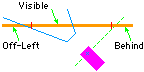
has turned so that the near end is behind the car, as in this diagram.
Cutting the wall in the middle (anywhere between the two red marks in this
diagram) cures the problem.
Caution:
Very long straight image wall segments may disappear if the car is angled
toward the wall in such a way that neither end is visible and one end is
behind the car. This is a consequence of one of the display optimizations
in deciding which wall segments to spend time on for display, and it may
be fixed in a later release. For now it is usually sufficient to cut long
walls into two or three segments, as described in the F1/10
example tracks page of this website. The problem usually happens with
image walls extending the full width or length of a room; when the track
curves toward the wall and the approaching car begins to straighten out
towards parallel, before the far end comes into view, but after the car
has turned so that the near end is behind the car, as in this diagram.
Cutting the wall in the middle (anywhere between the two red marks in this
diagram) cures the problem.
M -- One-cell Manual
wall segment --
Mt vv hh dd. ff+aa tt ww xx%^yy pp nn*
This operator is normally inserted into
the file by the curve operator macros. It specifies a single cell (usually
the corner inserted between two wall segments with different compass directions)
with a specific face defined by the dd parameter, which
should be one of the compass directions or 45o
between them (0, 45, 90, 135, ...); the wall face is the side of the cell
facing the compass direction, or else the diagonal through the middle and
facing in the direction of the corner. If you use the optional '.'
suffix on one of the diagonal directions, then the corner is a single-pixel
face corresponding to that direction. The remaining parameters have the
same significance as the 'G' operator, except some obviously
have no significance and are only placeholders. The optional '%'
tag on the image column position is used to signify that the image is to
be centered in the cell (the repeat '*' tag makes no sense and
should not be used when the image is centered). The optional second letter
't' after the operator name is either 'R'
or 'L' to signify whether the cell is part of a right-
or left-turn sequence. Alternatively, you can choose precisely which face
of the grid cell contains the visible wall segment using a single digit
for 't' thus:
0: The wall faces east
1: The wall faces south
2: The wall faces west
3: The wall faces north
4: The wall barely touches the northeast corner
5: The wall barely touches the southeast corner
6: The wall barely touches the southwest corner
7: The wall barely touches the northwest corner
8: The wall is a diagonal from the southwest
corner to the northeast corner
9: The wall is a diagonal from the northwest
corner to the southeast corner
10: The wall is a diagonal from the northeast
corner to the southwest (2 digits)
11: The wall is a diagonal from the southeast
corner to the northwest (2 digits)
You should take care that the digit you choose does
not contradict the compass direction dd that you chose.
Note that all of the multiple views for a single cell should be sequential
in your descriptor file, and their view wedges should substantially overlap,
because the different face angles you choose for them will result in different
perpendicular crossings and therefore different reference points for the
view angles, leading to small discrepancies in measurement; the overlap
covers for these discrepancies. The different view angles are considered
in file order, so the narrowest view wedges should be listed before the
wider default wedges in a single cell.
You can use the track image wall fragments in
the accompanying "TrackImg.tiff" file, for which the coordinates
and sizing for the current release are listed in the
"F-1/10 Additions" table in the "Image File
Coordinates" page of this website.
U --
Painted
Image -- U vv hh oo ff tt ww xx^yy
-- or -- U vv hh oo ff
tt ww
Artifacts have
a vertical dimension and a user-specified appearance, and (except for traffic
lights), if your car tries to occupy the same location, it will crash.
There is also a need for lines and other stuff painted on the pavement,
which are harmless to drive over yet which the autonomous car often needs
to see and understand (or perhaps intelligently ignore). You can paint
a modest number of images using the Painted Image operator. The location
of the northwest corner of an image fragment is the same as the usual vv
and hh parameters in (possibly fractional, resolving to
25cm) 2-meter grid units. You also specify some option bits oo,
currently two bits with a value 0-3 to indicate how many 90-degree clockwise
rotations to apply, plus a third bit +4 for high-res (32 pix/meter, otherwise
4ppm), and then either a line number ff in the image index
which contains an offset in the image file to the image to be painted and
its height and width in the
standard format, or
else zero and image height
tt and width ww
in pixels directly, and the image offset
xx^yy (vertical
offset
^yy required). You can also optionally override
the height and width (cutting pixels off the bottom and right edges) in
the index version. As with artifact images in the same file, the surrounding
white space is transparent, and you could conceivably overlay several images
on your track; the order of the painted image operators in the file determines
which images are "on top" (bottom to top). The images replace everything
in view except walls and artifacts (and the car avatar, when shown).
The default image resolution is one pixel for
each 25cm square of ground; the high-resolution option offers more detail,
at one pixel for each 3cm (about one square inch) of ground. You can rotate
your images automatically by 90 or 180 degrees; if you need other orientations,
you must supply alternate images. Image placement is still limited to 25cm
resolution; if you want more precise placement than that, adjust the position
of the pixels in the image by shifting the file offset xx^yy (as
in the "Divided Highway" track descriptor included in the distributed "TrackImg.txt"
file). Note that the height and width of an image is always (file) pixels.
You need to understand that if you rotate the
image, the tall & wide parameters in your operator line represent the
dimensions of the rotated pixels. For example if you are using a
horizontal image of a painted line to do a north-south dotted line (as
in the "Divided Highway" track descriptor), then you would rotate the image
(option +1, or in this example +5 for hi-res) and designate
tt=160
and ww=10 (because 160 3cm pixels tall is a five meter = 15-foot
stripe, and ten 3cm pixels = 10" wide, although only six pixels of width)
while the image in the file is the other way around.
If you want white paint on your floor or simulated
ground, you need to surround it with non-white pixels so the white pixels
are not changed to transparent, but you do not need to include those boundary
pixels in the images you paint. If you still want regions of transparency
inside the boundaries, you can use a magical color Transprnt
(currently specified to be near-white, 0xFEFEFE, but you could
choose any one of the 16 million available colors for that purpose) which
always becomes transparent. The distributed "TrackImg.tiff" example
image file contains a white-painted STOP line with
the word "STOP"
in front of it, as is commonly used in states without harsh winters. It
is oriented for northbound streets; add +1 for eastbound streets or +3
for westbound. Note that each region of white paint is surrounded by a
light gray border, and the two interior unpainted holes (in the "O"
and "P")
use the Transprnt color.
If you give the Painted Image operator a horizontal
position greater than the map width (128) but less than the window width,
then it (and the vertical) become window coordinates for whatever part
of the image you specify, and it is shown on top of everything else, unrotated
and unscaled, with the transparent portions black. It's meant as a debugging
tool, but you could also use it to put a logo or image version number in
some unused part of the window, just obviously not near the left edge.
The later additions to the TrakSim track descriptors
(ceiling and floor properties and luminance and line color) have no defined
place in the file format, so you can use
them only immediately, that is, in a text file that overrides the default
track index file.
Set Ceiling Height -- 9 mm
When your car needs to figure out where
it is (or correct for drift in its internal calculations), it may be that
you can find a landmark on the ceiling -- such as a pattern of overhead
lights or a chandelier. It helps if the simulated ceiling is properly colored
and positioned to find that landmark in. This line lets you specify the
hieght in park metters mm (the '9'
at the front of the line tells TrakSim that this line sets ceiling height).
You can set the ceiling color on a per-track basis using the BackWall
color descriptor line. Actual artifacts can be added as luminaries
(which are not required to illuminate the track, they can just be artifacts
floating up in the air or on the ceiling).
Ceilings were added late in the game, so the display
resolution is pretty poor in the distance, because the distance is calculated
based on the pixel row on the floor where the wall has its foot. This means
the side walls, where they meet the ceiling, the line is pretty ragged,
and the far walls are just plain wrong. I need to re-do the distance and
height calculation in a higher resolution, but it may not happen this year.
Sorry about that.
For having your car look for landmarks, it probably
will work anyway, because the effect is stable: every time your car comes
to this point in the track, the ceiling will look the same, just not identical
to the real track the simulated track is modelled after.
Floor Tile -- 8 pp tt ww xx^yy
Another artifact your car can look for
is a repeating pattern on the floor. This works like the pebble spec, except
that the pattern is repeated rather than pseudo-random. You specify the
top-left corner xx^yy of the pattern in the image file,
and what the repeat cycle is in rows tt and columns
ww and what the pixel size is as 2pp
pixels per park meter (for example, pp=3 is 23
= 8ppm), and TrakSim will tile the entire floor with your pattern.
Pebble Specification -- [n] 0xrrggbb
or[]
rgb rgb rgb rgb rgb rgb rgb rgb rgb rgb
Normally TrakSim will create an even
distribution of luminance across the specified contrast range for pebbled
track texture. However, you can include specific RGB
colors in your track descriptor if you are running it immediately (these
values are not preserved in the ".indx" file), either ten 12-bit
(hexadecimal) RGB values on one line, or else ten
numbered lines (n=0 through n=9), one 24-bit RGB
value each. These values will override both the specified contrast and
the track color itself (except when the track is distant enough to justify
using an "average" instead of individual pebbles).
Rectangle of Uniform Luminance --
= vv hh tt ww nn
The entire map is prefilled with the
value 2 raised to the power of
LumUniShif constant (12, so =4096),
which is the nominal base value (full illumination), but you can replace
it (or any rectangular part of the park) with your own base value, or over-write
some regions after you have specified other luminance parameters. The rectangle
filled is defined by the north (vertical) coordinate
vv,
west
hh, south tt, and east ww,
with a base level
nn between 0..4096 (or more, but higher
values will wash out your colors). The coordinates are in park meters,
not 2m grid coordinates, so you need to use twice the values of the grid
positions to match other map locations.
You can get gradients across the track by nesting
uniform luminance rectangles of slightly smaller sizes with slightly increased
(or decreased) luminance values, as for example in the "PSU
Stairwell" track. Point source luminaries automatically
generate gradients added to previous levels. These are important track
properties to test if you will be running your car indoors with uneven
lighting, or outdoors on a sunny day with shadows, because a luminance
gradient across the track makes the edge line detection particularly tricky.
If you specify any luminance in your track descriptor,
then every pixel derived from the track pavement or non-track ground cover
is scaled by the luminance at that point in the grid, which takes slightly
more processing time than when no luminance is specified. Any added paint
is similarly illuminated, but artifacts (like cars and pedestrians and
stop signs) are displayed at full luminance from the image file. Added
walls are illuminated in the map, but not in perspective ("camera" image),
for performance reasons and because your software normally doesn't need
to be looking at the walls anyway.
Luminance Point Source -- > vv hh
aa nn ff+dd<mm>ss tt ww xx^yy pp
You can add as many point-source luminaries
-- think: ceiling lights -- as you like, each with a location in park meters
(not the usual 2m grid coordinates) vv and hh,
and a nominal height aa in park meters above the floor
(5" actual, think: half-feet), and a brightness factor nn. For each
square park meter (5" square), the luminance in that square is the sum
of the base luminance in that square (so far), plus inverse-square-law
illumination from each defined ceiling light, where a total score of 4096
presents the track colors the same as if there were no luminance controls;
lower numbers darken the colors (down to black=0) and higher numbers tend
to wash out the colors. The standard room ceiling height (8 feet actual
= 20 park meters) with brightness nn=4096=(1<<LumUniShif)
is defined as the nominal unity, so lights closer or brighter will illuminate
more than if you defined no illumination at all, and higher or dimmer lights
will leave the floor darker. Artifacts like stop signs and traffic lights
are not illuminated, they always display as the file colors, but paint
on the floor (like painted lines) are subject to luminance control. There
is no provision for different-colored lights, because a self-driving car
typically would be abstracting out luminance only anyway.
Four optional numbers together as a single word
specify direction and radius; for a simple omnidirectionary luminary (no
aim specification), use a single
ff=0 as a placeholder.
To specify true north as a direction, use "360". Normally you
would also specify a field width
+dd in degrees to either
side of the center aim figure, but the default is 90 degrees (as if the
luminary is mounted on a wall facing in the direction of aim); "180" (full
circle, 180 degrees each way) is useful only if you need to designate a
maximum "<mm" or minimum ">ss" radius.
The radii are specified in park meters, effectively rounded to integers
because that's the size of the luminance grid cells. A lampshade can direct
the light downward, while blocking light outside a particular radius; use
the maximum radius
<mm to create that effect. A hanging
lantern typically has a dark circle directly under it where the fuel tank
blocks the light; you can use the minimum radius >ss to
create that effect. A light near the end or corner of a wall will cast
a shadow of the wall on the floor; you can use the aim and deviation ff+dd
to create that effect.
If you include optional pixel size tt
(tall) and ww (wide) and xx^yy (row+column
position in the image file, see Artifacts below)
and pp (pixels per meter), then TrakSim will attempt to
display the image of your luminary in the right place on the screen.
A point-source lamp at aa=20 (park)
meters above the floor with a specified brightness nn=100
will add +100 units to the luminance of the square directly under it, and
proportionately less as you move farther away. A total of 222 (the LumUnity
constant) for any square means that the colors defined for that piece of
track or non=track will show normally; a higher number will brighten (possibly
wash out) the colors there, and a lower luminance factor will dim them.
To simulate a single ceiling light in the center of a standard house ceiling
eight feet above the floor (approximately 100" = 20 park meters) in an
otherwise dark room and achieve maximum brightness (=4096) directly under
the light, you would need to specify a lamp brightness of 4096x12
= 4096. In reality, white walls will reflect some of the light hitting
them back into the room. so you'd probably want to start with an ambient
("uniform") light level corresponding to that effect,
where half as much light hits (and reflects off) the walls of a 20' square
room as hits the floor in the middle, so you'd specify an ambient "uniform"
level of 2000 + point-source brightness somewhere around 2000. The edges
of your room would be about half as bright as the center.
Lamps higher than 1Km (1000m) will give a uniform
illumination anyway, so you should use the Uniform Luminance rectangle
operator instead, unless you need a circular or wedge shape for the illuminated
area.
Artifacts always display
at normal luminance (file colors), the luminance operators have no effect
on them. Paint on the pavement, however, is affected.
The illumination operators are fixed to the landscape
-- no moving lamps -- but you can leave the car stopped to test a pair
of lights with a narrow wedge of illumination at a particular place in
the track, see "Headlights" in the Figure-8 track
(commented out as distributed). You can use luminance operators with brightness
nn=0
to float artifacts above the track without adding extra computation time
for luminance.
Wall Color -- < 0xrrggbb PilasterCo
CeilingCo CreamWall DarkWall
You can override the BackWall
and other wall colors set in Java class "DriverCons" on a per-track
basis, but (like the Pebble Specification) only if you are running it immediately.
Simply give it an RGB value as a single hexadecimal
integer. If you want black walls, you need to be satisfied with 0x010101
or very dark blue (0x000008) because integers less than 8 won't
work. Optional additional numbers respectively set PilasterCo,
CeilingCo,
CreamWall,
and DarkWall.
White Line Color -- ] 0xrrggbb
You can override the WhitLnColo
set in Java class "DriverCons" on a per-track basis, but (like
the Pebble Specification) only if you are running it immediately. Simply
give it an RGB value as a single hexadecimal integer.
Coefficient of Friction -- ` 0.cc
You can override the CoefFriction
set in Java class "DriverCons" on a per-track basis, but only
if you are running it immediately. Simply give it a fractional value greater
than zero and not much greater than one.
Track Operators
The track that your simulated car drives around is
defined by tracing out (straight) line segments of its right edge, that
is the edge that if you are facing in the direction of advance, the right
edge begins where the previous advance left off and ends in the cell specified
by that operator. The track is defined to be to the left of that edge,
and non-track is to the right (the white line is exactly on that straight
line from start to end). Unless specified with a decimal point, track edges
start and end in the middle of whatever side of the cell faces in the direction
you are aiming.
There are four compass directions which a track
edge can be generally aiming, and at the end of a segment in any of those
four directions, the end of the track edge currently being defined ends
on the specified final grid cell at the edge corresponding to the direction
of advance. For example, the Northward advance operator ends at the middle
of the north edge of that cell, unless a fractional cell position is specified,
in which case that is the endpoint. The endpoint is significant, because
the next track advance operator resumes from there to its own endpoint,
effectively drawing a straight line from point to point in the order specified.
There are two ways to do a track. The "easy
way" uses only the (full) Left/Right, and Advance
operators, except for a single directional point to start each complete
edge. The result is a track with 90-degree turns (of whatever radius) and
straight edges in the four compass directions. You still need to (separately)
add up the total Advances in each direction (so east and west come out
the same, and north and sourth likewise). The curve radius is the amount
of advance in the new direction; the previous direction is also advanced
by the same radius +1.
For a more interesting track, you can use partial
curves and the compass operators, but it requires a lot more attention
to where each track edge segment ends up. In the example tracks, you can
see that I used comments to indicate where I thought each segment ended.
In some cases I went through the console log looking for lines tagged "[*]=>"
which gave the endpoints of each generated intermediate line segment.
You need to be careful that each compass segment
starts off in a direction compatible with where the previous segment left
off, because the edge generation tool cannot put more than one track edge
specifier in any single cell. This makes for a very efficient way to draw
the scene: map cells that are nowhere near a track can be quickly determined
to be non-track, and similarly map cells within the track but not near
an edge are quickly determined to be so; only those grid cells the
track edge traverses require extra processing to determine which side of
the edge this particular pixel is (and therefore which color to paint it).
But it also means that if the logical track edge crosses the cell more
than once -- by advancing to a far side, then returning to a near side
-- only one of those lines can be contained in the map data, and your displayed
track will have discontinuities. Paying attention to this turns out to
be more complicated than it might seem. For this reason we have the advance
macros for doing compass straights and reasonable turns automatically.
But first the basic compass operators.
N -- Advance
track edge Northward -- N vv hh
S -- Advance
track edge Southward -- S vv hh
E -- Advance
track edge Eastward -- E vv hh
W -- Advance
track edge Westward -- W vv hh
The main purpose of the compass direction
name is to tell the track generation tool which edge of the final cell
to end at. The final cell is specified by a grid (2-meter) coordinate;
the start of each edge segment is defined by the end of the previous track
edge segment. The first edge operator creates no edge segments, but only
defines an end for the next operator to build on. Every track definition
must begin a track edge specification with a single compass direction to
tell TrakSim where to begin and which direction you intend to advance from
there. After that you can specify most or all of the track by Advancing
in the current compass direction for some number of 2-meter grid cells,
with Left and Right curves interspersed as needed.
I -- Initialize
as no prior -- I
X -- Erase
overstrike prevention history -- X nn
Every operator to advance the current
track edge builds on the previous endpoint. That's well and good for completing
the outside perimeter, but you need to restart the edge of each inner island
of non-track as unconnected. The Initialize operator does that.
When the advance of a track edge crosses exactly
through the corners of two diagonally adjacent cells, the white line as
drawn might pinch out to nothing there unless the other two cells at that
corner are also encoded as track edges. If the track turns at that corner,
the logic to add those extra cells can overstrike actual track edge, so
the simplistic (and reasonably effective) solution is to keep a modest
record of recent grid cells into which track edge has been encoded. Normally,
there's no problem, but if you are doing some tricky track edge positioning
-- such as for a fork in the track -- the overstrike prevention leaves
ugly gaps in the appearance of the track. If you erase the history, you
can subsequently specify additional edge lines to override previous generated
edges. The number you give it holds off adjacent cell filling for that
many more advance lines, which prevents new advance lines from overstriking
nearby cells. You don't need to use the erase overstrike prevention history
operator if you are building simple loops, only for tricky track shapes;
normally you insert it after you see nearby track edges leaving holes in
the track edge.
A -- Advance
track edge -- A nn
L -- Curve
track edge to the Left -- L rr ee-ss
R -- Curve
track edge to the Right -- R rr ee-ss
These are macros that analyze the current
track edge position and generate one or more compass operators as appropriate
for advancing the current edge in the specified relative direction. Advance
goes a minimum of one cell in the previous direction.
The curve operators nominally curve left or right
around the specified radius rr. Unless you specify optional
ending ee and skip ss angles, the curve
starts in the current compass direction and ends in whichever compass direction
you tell it to turn to after turning 90 degrees. You can tell it to end
early ee which is an angle between 6 and 90 degrees; if
you ask it to stop at an angle not defined for that radius, it will try
to interpolate whatever segment crosses that nominal angle. If you specify
an ending angle, you can also (in the same word, no spaces) tell it to
skip some number of segments before starting, by giving it a start angle.
This diagram shows the current specified angles for exact match in each
defined radius. Note that the angles are not exact, but adjusted so segments
start and end on cell boundaries:
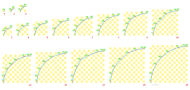
There are sixteen defined radii (0 to
15), and the larger radii appear smoother because segments are limited
to integral numbers of grid cells, which you also can skip either at the
beginning or end of a curve (or both). For example, if you tell it to curveLeft
radius 8, end at 80 degrees and skip 6 degrees at the beginning ("L
8 80-6") it will round the skip angle to the nearest cell boundary,
in this case probably closer to 7 degrees at the beginning and 75 at the
end.
The total advance of a full curve is determined
by its radius, which is that many grid units in the new direction, and
one more than that many grid units in the previous direction. Thus a full
(90-degree) curve Left radius 8 from facing north at grid
15,20 (as would result from the track operator "N 15 20") would
advance in the new (west) direction 8 units (decreasing, to 7) and in the
prior (north) direction 8+1=9 (also decreasing, to 11) for an end position
facing west at 7,11. Another curve, radius zero, immediately turning to
the right advances one more position (0+1) west but none back in the new
direction to the north, leaving you facing north at 7,10.
When laying out your track you need to keep the
track width in mind, because the inside track edge will be smaller in both
the horizontal and vertical directions by double the width of the track.
If your track is to be three grid units (6 park meters = 20' or 30" on
the floor in 1:8 scale) wide, then you might lay out the outside perimeter
30 grid units in each compass direction -- for example using four Left
8 operators alternated with four Advance 13 operators -- and then
restart the inner edge three units in from wherever you started the outer
perimeter, but reducing the curve radius by 3 in each case. The resulting
track descriptor (see "RoundRect" in the examples file) might look something
like this:
W 1 10 -- start outer perimeter facing
west
L 8 -- curve south to 9,1
A 13 -- advance to 22,1
L 8 -- curve east to 31,9
A 13 -- advance to 31,22
L 8 -- curve north to 23,31
A 13 -- advance to 10,31
L 8 -- curve west to 1,23
A 13 -- advance to 1,10 = start
I -- new track
edge
E 4 9 -- start inner circuit facing
east
A 13 -- advance to 4,22
R 5 -- curve south to 9,28
A 13 -- advance to 22,28
R 5 -- curve west to 28,23
A 13 -- advance to 28,10
R 5 -- curve north to 23,4
A 13 -- advance to 10,4
R 5 -- curve east to 4,9
= start
Since the minimum radius is zero, if the outside
curve is sharper than the track width, you will need to compensate by reducing
the advance going into the inner (radius zero) corners by the difference
between the outer radius and the track width. Generally you should design
it as well as you can, then let TrakSim build the track, and then look
at what it did to see how to tweak your parameters to get what you want.
Partial curves reduce the advance as indicated
by the yellow checkerboard in the diagram, where each square represents
one grid cell. As you can see for the previous radius 8 partial curve ("L
8 80-6"), 15 degrees skips over two of the nine grid cells going north,
but it would be interpolated to one skipped cell, and 75 degrees omits
the final two of eight grid cells going west, so the end position would
be facing westerly at 10,13. If you end a curve at 45 degrees or less,
or if you start your curve after (but not on) 45 degrees, then the orientation
does not change. You need to keep that in mind if you are concatenating
partial curves: to straighten out from a partial curve that ended before
45, you need to resume in the opposite direction (right for left or left
for right) beyond 45 degrees (so that the ending angle and the new skip
add up to 90); to straighten out a partial curve that went past 45, you
need to resume the corresponding angle before 45. Similarly, to continue
a partial curve at a different radius (like if you are simulating an elipse
or egg shape with gently curving sides and sharply curving ends), you should
begin at or near the angle you left off.
A comprehensive example of simple curves is made
up from two basic circles joined into a "Figure-8"
with added artifacts, which are discussed in the next section on Artifact
Specification. Partial curves of various radii are exercised in the
new "Brussels" track.
As indicated above, these three advance operators
are macros, that is, their operation is to generate one or more compass
edge segments. You can observe the generated operators in the console log
(look for lines tagged "[*]=>") if the MapLogged switch
in the Java class "DriverCons" is set to true. Looking
at the generated operators can be very helpful for thinking about how to
add diagonal edges; you can see an example of that process in the analysis
of the "PSU TestOval" track below.
Fractional Positions and Sharp
Corners
The track edges built by these tools only approximate
what a real track might be like, which we suppose is "good enough" for
a simulation of this caliber. Partly because the park map grid is 2-meter
squares, and partly because the native resolution of the track building
tools was initially integer grid coordinates -- we now do 25cm resolution
in the track edge building tools, but are still limited to a single straight
edge in each grid cell -- the track edges are somewhat blocky. I suppose
with more time and resources to expend on this simulator, we could do 3mm
resolution in the track building tools (which is the limit for diagonal
line precision in the current encoding) and accordingly better curve approximation,
but for the kind of steering precision possible in an actual autonomous
car, what we have is generally adequate.
Fractional positions in track edge operators are
accepted if one or both the vertical and horizontal coordinates contain
decimal points, but the resolution is currently limited to 1/8th grid cell
dimensions (25cm). When integer coordinates are specified, the ending points
are the middle of their respective faces; with fractional coordinates the
endpoints are still on the respective faces, but you specify where along
that face.
One of the casualties of this lack of precision
is the difficulty in making sharp corners in the track. If your image processing
needs to discern true corners in the track edge -- perhaps such as the
notch in a fork in the road -- and if you can tolerate careful management
of the placement of those corners, corners are possible. The key issue
to keep in mind is that each cell can encode only a single straight edge,
so your corners must coincide with 2-meter grid cell boundaries. Furthermore,
the compass operators always leave the current point at the edge of the
cell named by the operator -- for example a Westward operator leaves the
current position on the west edge of the final cell of that run. A diagonal
edge designated as westward, but advancing more southward, then resuming
northward and only slightly westward, will leave a reasonably sharp corner
there.
Consider the track descriptor "Divided Highway"
in the file "TrackImg.txt" which is a short segment of a two-lane
bidirectional north-south track that switches to a divided highway in the
middle. The vertex of the divider end is on the boundary between cells
(14,5) and (14,6). Track is always built tracing the right edge, so this
vertex is approached from the north along the divider, then tilted slightly
west, then turned sharply northward again.
The "MinimalSquare" track descriptor
in the distributed file "TrackImg.txt" shows an example of using
fractional track edges to butt two orthogonal edges up against each other
in lieu of a proper corner.
Q -- Convert
track to non-track -- Q
To create a park area with non-rectangular
borders, start by laying out what looks like an outside track edge that
closes in on itself, then Bucket-drop track (or non-track) into the enclosed
area, then convert the track to non-track, which converts both pure track
cells and edge cells into non-track cells, which is now your odd-shaped
park. Then you can add real (unconverted) track on top, as well as walls
and artifacts. The track boundaries of the default "PatsAcres" track in
the distribution were created this way.
Artifact Specification
The original idea was to specify objects with elevation
above the ground (other than the simulated car itself) as part of the cell
structure of the track, but that idea fell to the triage axe. Then it became
evident that we needed to support not only static objects like trees and
hay bales and spectators around the sides (as seen in downloaded images
of the PatsAcres go-kart track), but also pedestrians walking across the
simulated car's path and maybe even traffic lights that change from green
to yellow to red and back on a regular schedule. So artifacts are back
in, but on a more limited scale. A 4-bit number identifies the artifact
type, which might be a traffic light or an immobile stop sign, or else
one of eleven animation sequences.
The information for building an artifact in your
track data is divided between track operator text lines which specify the
time and space parameters for a particular artifact, and the image specification,
which is further divided between an image fragment in a larger collage
of artifact images (the file "TrackImg.tiff"), and some index
lines telling TrakSim the position, size and scaling for each image fragment.
There is a single Object specification line for each phase of an animation,
or each directional view aspect of a static artifact. This is long and
detailed, so there are macros which require less detailed specification,
and which get the rest of the information from the "StopInfo"
block of image fragment descriptors -- essentially an index into the image
file -- at the end of your track descriptor.
First the operator lines:
Y -- Macro
to build static artifact -- Y vv hh ss aa!
@ -- Macro
to set Time & Position for an animated artifact -- @ vv hh ss ff+aa!
ee
Artifacts (anything to be drawn on the
screen, other than the floor, track and walls) are specified generally
by the grid cell position where they are drawn, plus the graphic information
for drawing them. Most of the graphic information for each artifact is
contained in a line of the image index (the "StopInfo" block of
image fragment descriptors), which refers to one of the artifact images
from the collage in a separate file; the particular line of the index may
be specified in the track operator line, or else (in the case of stop signs
and traffic lights) it is hard-wired for the type of artifact.
Artifacts are further distinguished by whether
they are static (stay in one grid location, 'Y') or else ('@')
dynamically appear to move, encoded as a sequence of static images distributed
over space each at a particular time in the simulation. The kind of artifact
is further determined by its reference number ss.
Reference number 0 is a stop sign (or any other
single object if you so choose), and its images are specified in the first
six lines of the index block, which separately designate what it looks
like full-on, full reverse, diagonal front and back, or else edge-on left
and right. The file "TrackImg.tiff" and the built-in index block
(if you do not include a replacement in your track descriptor file) comes
with a set of credible stop sign images.
Reference numbers 1, 2 and 3 are used for traffic
light specification; you specify only #2, the others are filled in automatically
using lines 7 and 8 of the index block. The light cycles automatically
on a power of 2 seconds (4, 8, 16, etc) as specified in the xTrLiteTime
parameter in the Java class "DriverCons".
Reference number 4 is reserved for starting a
timing sequence that forms the basis for reference numbers 5-15, and is
defined using the Start
Timing sequence operator
(below).
Reference numbers 5 through 15 give you up to
11 distinct animated motion artifacts, each with a specific line number
ff
in the index block, which may be the first of several views, and ending
at a particular expiration time ee relative to the sequence started
by the currently active sequence timer (or else tt=0 for this
particular line to remain active until the end of the simulation). The
'J'
macro is normally used to specify a whole sequence of times and positions
for your motion animations in a single track operator, giving your artifact
relatively smooth and linear motion across the screen. TrakSim does not
currently support multiple views on animated artifacts, it is assumed that
the animation plays for the simulated car in a particular position or range
of motion, and that your animation already has selected the views appropriate
for those view angles.
Reference numbers 16 and higher can be used for
arbitrary static artifacts, where the reference number designates the line
number in the index block you provide as part of your track descriptor
file. Multiple view images can be used for the same artifact reference
number, as distinguished by the view angle and view range given in the
index lines. The orientation angle aa is used by TrakSim together
with the relative position of the simulated car and the view ranges you
supply to select an appropriate view for presentation. This works the same
as for the stop sign, which is essentially a hard-wired special case. An
optional ! attached to the end of a parameter causes this artifact
to trip the proximity detector (if enabled and sufficiently close to the
car).
J -- Macro
to build moving/animated artifact sequence -- J vv hh ss nn ff zz dd
rr ee ii pp*xx
Although this looks big and scary, it's
much simpler than putting together a zillion individual '@' operator
lines. Each of the five parameters of the '@' operator line are
the same here, and are directly used in the first generated '@'
operator line. Then
nn-1 more '@' operator lines
are generated, with the position incremented by the radius rr
in direction
dd, using line ff+1 of the
index block (and its successors, until line zz has been
used, then cycling back to ff, as many times as necessary)
with an initial expiration time ee increased by ii,
which cannot be less than the
FrameTime
defined in Java class "DriverCons". If the radius is less than
the 25cm resolution of the display engine, the fractional parts are accumulated
and rounded for best motion accuracy. Direction angle dd is in
degrees clockwise from North, and the artifact (pedestrian or car or whatever)
moves in an approximately straight line in that direction, by one radius
per time increment
ii.
Making multiple views work properly turned out
too difficult for the available time and resources, but you can optionally
specify a fractional and/or negative step value pp to increment
the index line number from ff to zz, (and an optional
initial index *xx between ff and zz),
and it will repeat (or skip) index lines as necessary. If your index is
in a rotational order, you can effectively have different views of the
same artifact presented appropriately along the way as it morphs from approach
to departure.
You can search the console log for lines tagged
"{..}" to review the generated '@' operator lines.
At the end of the sequence the artifact is removed
from the scene, but you can add a final '@' operator line (or
even more 'J' lines) with the same reference number after the 'J' operator
line, and if it has a zero expiration time then it will specify what is
continually shown after the timed sequence ends. A sequence of 'J' operator
lines with varying directions (and/or varying radii) can display the artifact
wandering around in a non-linear way, if desired.
O -- Object
specification -- O vv hh aa! rr tt ww xx^yy pp nn ss ee
Although you probably will not be creating
any 'O' operators in your track description, it often helps to
see what the macros need to generate. As in the macros, vv
and
hh are the grid coordinates, aa and
rr
are the view angle and range used to select one of many 'O' operators
from the list for the same coordinates, tt and ww
are the pixel dimensions of the image, xx^yy is the position
of that image in the file, pp is the resolution in pixels per meter,
nn
is the artifact type number, ss is an internal reference
number, and ee is the expiration time. An optional!attached
to the end of a parameter causes this artifact to trip the proximity detector
(if enabled and sufficiently close to the car).
T -- Start
Timing
sequence -- T vv hh bb ss rr
The animated artifacts are specified
by a sequence of '@' operators, each specifying a position and
an expiration time. The time is defined by the sequence timer, which counts
eighths of a second from the time it is started. A timing sequence is normally
initiated when the simulated car crosses some horizontal or vertical position
(or both), either Eastward or Southward, or else Westward or Northward
-- or rather when tested, the car is on that side of the threshold, without
consideration of whether it recently arrived or was already there. The
number bb is made up of the sum of four bits:
+8: The car must be South of
the vv coordinate to trigger
+4: The car must be North of the vvcoordinate
to trigger
+2: The car must be East of the hh
coordinate to trigger
+1: The car must be West of the hh
coordinate to trigger
When all of the specified conditions are met, this
sequence is started with an initial time ss seconds. You can trigger
any number new timing sequences, which are numbered initially 0 and then
sequentially as high as needed, each as specified in rr.
It is recommended (but not required) that your initial times ss
be in ascending order for successive sequences; if they are not, it may
be difficult to properly sequence the animations depending on these times.
The timing sequence start operators are processed in the order they occur
in your specification file, one pass for each new frame build, but they
trigger in numerical order, which allows you to set overlapping trigger
conditions without interference. For example if they are physically in
reverse numerical order in the file, then each new trigger will affect
a complete object placement (screen redraw) process before the next timing
sequence is tested. If necessary you can include intermediate trigger conditions
such as the simulated car crossing some easily specified lap point before
it reaches a trigger position that might otherwise be hard to specify by
a single quadrant of the park map.
"StopInfo" Image Index
The artifact operator lines specify location and
orientation (and time) for the artifact images; the rest of the numerical
specification is (or can be) encoded in the lines of the index block of
image fragment descriptors. If you are satisfied with the default stop
sign, traffic light, and pedestrian images in the distributed "TrackImg.tiff"
file, you can rely on the default index block embedded in the "TrakSim"
Java code. Otherwise you can extend or replace the example index information
to correspond to your own images in a replacement, possibly enlarged, "TrackImg.tiff"
file. This section tells you how to do that.
The image index is identified in the track descriptor
file by ".StopInfo" in a line by itself (no spaces) after the
final track operator line. The period terminates the processing of track
operator lines (unless previously terminated by a period line), and the
index is itself terminated by a line that begins with two periods separated
by a single space. You can use a single index block for the entire track
descriptor file provided that there are no index terminator lines before
it.
The index itself consists of ten or more lines
of a half-dozen or so numbers each. Except as noted, there must be
spaces between numbers and at the front and end of each line, but extra
spaces are ignored. You may include a comment after any line, but it should
follow the final space; comments begin with a pair of hyphens and end at
the end of the line. The lines mostly consist of fragments of extended
track operator lines, that is, the macro artifact operator lines use these
lines to finish out generation of the internal artifact operator lines.
Each of the active lines must have the required portion of these parameters:
rr+aa! tt ww xx^yy pp~nn
where
rr is the range of view
in degrees from 8 to 360, or else 0 (meaning 360),
+aa
as a suffix to the range parameter is an additive to the orientation supplied
by the artifact operator, and
! as
a suffix to this parameter causes this artifact to trip the proximity detector
(if enabled and close enough);
tt and ww is
how tall and wide the image in the file is, in pixels,
xx is the offset of the image
in pixels from the top-left corner, or else its horizontal position, and
^yy
is the (optional) vertical position, default 0 if the image begins on the
top line,
pp is the resolution of the image
in pixels per meter when displayed at full resolution;
~nn is the line number, used
to validate the index,
=nn is the operator reference
number of a group of related images beginning on line nn.
You should preserve the first ten lines as
distributed except as necessary when substituting alternative images; your
added images will follow this pattern. Note that the four special characters
each join two (or more) numbers into a single word. This is important because
the parameters are extracted by word count, and optional parameters need
to be identified without upsetting the normal word count.
Multiple view images can be used for the same
artifact reference number, provided they are in successive lines of the
index. They are distinguished by the orientation (adder) angle
+aa
and view angle range rr, each being considered in order
until one of them specifies a direction and view range wide enough to encompass
the simulated car, that is, that view should be what the car sees at this
relative position. The adder angle
+aa is in degrees clockwise
from the direction the artifact is facing, that is, to the right from its
perspective. The range
rr is in degrees total view angle,
which is divided equally to the left and right of angle
aa.
Specify range 0 on the last view as a default in case no previous views
are acceptable. If no views are in range, then the artifact is not shown.
Be sure to include the "=nn" designator (where "nn"
is the line number of the first index line in the collection) which is
also the reference number, because that's how the software knows these
index lines belong to a single object.
As an example, compare the image index (in the
distributed "TrackImg.txt" file) to the stop sign images in the
distributed "TrackImg.tiff" file. All six of these images begin
on the first pixel row of the file, and represent front and back, left
and right, and diagonal views. The front and back each range +/-45 (total
90) degrees from straight-on front or back, then a second (horizontally
shrunken) image is used for the diagonal views between 45 and 80 degrees
on each side (total 160, but excluding the 90 degrees already caught by
the earlier lines). Finally an edge-on side view is offered for the remaining
20 degrees of each side. Notice that the last line is formally a catch-all
full 360 range, even though only 20 degrees ever get used. Notice also
that there are two different image sizes, with corresponding different
specified resolutions. Images likely to be displayed close to the viewer
(like the front of a stop sign the car is approaching) should be in a higher
resolution than is needed for images only seen more distant, or for which
the additional resolution is unimportant.
Most of the images you add will be indexed in
lines 16 and higher. Each 'Y' artifact operator line should refer
to its corresponding index line for access to the particular image corresponding
to that view angle. See the "Figure-8" track descriptor
for an example of a car parked by the side of the road facing west. If
you start up in that track with the close-up map enabled, you can click
in the lower close-up map to direct the aim of the car, and in the smaller
park map at the top of the window to place the car. Judicious clicks in
the two maps let you migrate the car around the parked car (while facing
it), so to see how the display engine scales the images according to the
distance, and the views according to where you are looking at it from.
Try changing the coordinates and aim of the 'Y' artifact operator
line on the car to see how that affects the display.
The same car image is used in a 'J' animation
sequence where the car drives by on the crossroad as you approach, while
a pedestrian walks across the road in front of the parked car. These are
described in more detail in the "Figure-8" track descriptor
example below.
Your images in the "TrackImg.tiff" file
need to be non-overlapping in rectangles of white space which extends eventually
all the way to the four edges. The WhiteAlfa
method converts contiguous white space into transparent alpha channel,
so if you want white at the edge of your image, you should surround it
with something non-white (0xFEFEFE is very nearly white, but will
fail to convert to transparent). You should specify in your index the top-left
corner of the closest containing rectangle, and the rectangle dimensions
for height and width. Images are displayed by skipping or replicating pixels
-- which is much faster than blurring inexactly aligned pixels -- so if
you have a single vertical centerline that should always be displayed,
make sure your rectangle has an odd width centered on that vertical line.
For example the stop sign may be shrunken substantially in the distance,
but it will always show the post line and at least one column of red above
it (at maximum park distance = 320m, the 2m height will display at least
4 pixels high on a 640x480 window).
The images in the distributed "TrackImg.tiff"
file are rather crude (having been cobbled together by a non-artist ;-)
so you are free to replace them with better art, preferably better than
the car images I scraped from the internet under the "Fair Use" doctrine
of the copyright law.
Beginning in 2018 June, the distributed "TrackImg.tiff"
file includes a revision date in pixels (currently near the lower left
corner). You should make sure the file matches the code dates, as some
image positions are hard-coded.
Debugging Your Track Descriptor
File
TrakSim is not a friendly program and it's easy to
make mistakes. Fortunately, once you have a workable track map, you don't
need to do this again, except maybe an occasional tweak. In this section
We review a few heuristics for making sure the map is what you want.
If you've laid out a track and it doesn't look
like you planned, you can use a technique I call "Lion Hunting" from an
old mathematician's joke: "How does a mathematician hunt lions in a forest?
He divides the forest in half; either the lion is in this half or that
half. Then he divides the half where the lion is into half again (now two
quarters) and repeats the question, until finally the section of the forest
is so small, all you can see is the lion. In finding problems with your
track descriptor, place a period at the front of a line about the middle
of your descriptor (halfway to the normal terminator). If the resulting
track looks OK (for the operators still there), then the problem is in
the back half, and you can divide that half in half, otherwise it's in
the front half. Repeat until you have found the offending line.
If some view facet of an object disappears, check
its index line: if it points to a blank part of the image file, nothing
will show. If you left out a required parameter, the whole line will be
ignored or effectively deleted.
The map building tool does some minimal checking
for inconsistent or invalid parameters, and tries to ignore the errors.
If you notice that some track specification is missing, make sure the MapLogged
switch in the Java class "DriverCons" is set to true.,
then search the console log for lines containing the tag "<??>"
which often flag found errors. Immediately to the left of this tag is an
error number in the form "*-00)" except that "-00" represents
an actual negative number between *-2 and *-99; you then
search the source code of the BuildMap method in Java class "TrakSim"
for a line containing "rpt = -00" (but with the actual number)
and read the nearby comments or other clues for the cause of rejection.
The console log line after the "<??>" usually contains the
offending source line enclosed in apostrophes (single quotes), usually
with your original comment preserved on generated lines.
The first number on lines tagged "(BildArt)"
or "(BildMap)" is the file line number, but it will be increased
by generated lines if you use macros. Nevertheless, you can think in terms
of relative line numbers back (or forward) to a unique comment to help
find the offending line.
If your whole image index disappears, check the
log for a line "** Invalid StopInfo" which is also tagged "<??>"
just after the offending line.
If you are into searching through somebody else's
code to find a problem, it might help to understand that many of the methods
are organized as a sequence of steps with numbered error checks (the variable
"why" is incremented, and thus represents the error number in
that method), then at the end, the error number (or zero, if no error)
is logged in the console log (among other parameters useful in debugging
but probably no longer helpful) after an "="; searching through the method
code for "why =" will generally locate the problem condition.
There are vaious final boolean switches in the Java class
DriverCons to turn those error summaries (and other diagnostics) on
or off. The console log becomes impossibly long (and slow) if they are
all turned on, which is why most of them are turned off after the code
seems to work correctly.
If you are having problems with the display of
images, you can use the
Painted Image operator 'U'
with a horizontal position greater than the map width (128) but less than
the window width, and then it (and the vertical) are window coordinates
for whatever part of the image you specify, and it is shown on top of everything
else, unrotated and unscaled, with the transparent portions black. It's
just a debugging tool, but I suppose you could also use it to put a logo
or image version number in some unused part of the window.
Examples
The first two descriptors in the track descriptor
file "TrackImg.txt" are discussed separately below. First we will
touch lightly on the other example track descriptors.
The third example descriptor "Minimal Circle"
consists of nothing more than four 90-degree turns connected with short
straight segments into an approximate circle. It is useful for studying
how the track macro operators make curves, so that you can build more complex
tracks with diagonals and other kinds of curves, as in the first two examples.
The fourth example descriptor "Divided Highway"
illustrates sharp corners in the track, such as one might find in the real
world where a two-lane country road splits into a divided highway. It also
shows how to make dotted lines in the track using the Painted
Image operator. in this case we want the painted line split across
the cell boundary, but not as wide as the (low-resolution) placement parameters
would make it, so it uses part of the yellow stripe in the distributed
"TrackImg.tiff" file, but includes some (transparent) white space
to effectively shift the partial paint over to be centered on the grid
cell boundary, and thus to line up with the divider.
The first stripe is rotated counter-clockwise
90 degrees, so the 5-pixel transparent region (above the yellow stripe
in the file) is to the left of the displayed stripe and effectively positions
the paint five pixels to the right of the specified horizontal coordinate
(5.9 grid units, rounded to the nearest 25cm = 5.875). The second stripe
is rotated clockwise, so it's harder to understand: the pixel width counts
backwards from the next 1/8th grid coordinate, and the blank space below
the stripe shifts the paint to the left. It's much easier when rotated
images fill the 25cm grid units, that is, you are using images that are
an integer multiple of 32 pixels (including transparent regiousn at the
edges).
The fifth example demonstrates the use of fractional
edge coordinates.
Figure-8 With Artifacts
When you are creating a new track for TrakSim, it
helps to do a little at a time. I try to do the perimeter first (after
the initial park fill), then insert a track-end line and run it through
the BuildMap method to see if I
succeeded in getting the track to close on itself (usually I fail the first
few times). Then I add the inside islands and look again.
In this case I started with two copies of the
"Minimal Circle" then converted the southeast corner of the upper one and
the northwest corner of the lower one into straights to meet at the crossroad.
My next thought was to erase the crossover edges using the Fill operator,
and that was OK (see the "Minimal Square" track example), but then I decided
a cleaner solution is to do a hard right turn at each corner of the crossroads.
That way the whole track can be constructed from Advance and turn operators.
In both cases it took several attempts to get the track to close properly.
Then I drop a bucket of track inside and look
again. If the track is narrow, or if I failed to get the inner loops spaced
correctly to the perimeter, the bucket drop may not reach the whole track.
Narrow lanes are not unusable, but you must put more effort into filling
it. If the whole track is narrow, it is sometimes easier to bucket the
track after the outside perimeter is complete, then bucket non-track in
each island after the island perimeters are closed.
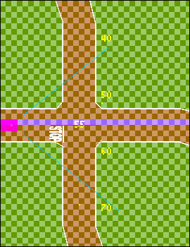
The next step is to add the artifacts. Especially
when you build the track edges using relative track advance macros, it's
hard to get the artifact placement correct. I found some help placing "milestones"
alongside the track, like this enhanced screenshot. I left these in the
file but disabled, so you can see how to use them. Notice they give the
coordinates in park meters, although the operator coordinates are in 2m
grid units. You could do them in grid coordinates if that helps.
If you look carefully in this screenshot, there
are two obvious yellow dots (artifacts), one near the 50 milestone, which
is the pedestrian before he starts walking, and the other in the middle
of the track even with the 70 milestone. It was tricky to get these animations
to pass by before the simulated car got to the intersection, and the initial
placement was a large part of that (there may be slight differences in
the distributed file).
Much harder to see in this screenshot are the
two artifacts (the parked car near the pedestrian, and the stop sign) that
are right on the white track-edge line. The traffic light also has a yellow
dot in the middle of the street, but it's right next to the milestone which
is the same color.
You can dynamically reposition the car avatar
to be looking at some part of the track up close. With the ShowMap option
turned on, click in the upper map to place the car, and in the lower map
(if showing) to change its orientation (it will turn to face where you
clicked).
It's easier to place your artifacts and paint
images one at a time, then disable them while working on the next one.
The TrakSim Java class code contains an image index
suitable for everything here in the Figure-8 track -- indeed, for all the
tracks in the "TrackImg.txt" track descriptor file -- but the
index lines relating to the car images are commented out. If you have no
plans to replace this car or to add other artifacts, and if you make much
use of my car images, you could simply uncomment the extra lines.
I set up four stop signs and four matching painted
STOP
words for use on the street, but enabled only the one facing the initial
car position. As I said, placing these things is tricky. I made a guess
for each one, then fine-tuned the placement after seeing what TrakSim did
to my handiwork.
If you need an overhead traffic light placed on
an intersection of streets in compass (N/S/E/W) directions as here, and
if you are satisfied with E-W starting green (N-S red), you don't need
to worry about rotation. Otherwise turn it 90 degrees. Of course if your
intersection is for streets on a diagonal, you need to rotate the traffic
light to face the respective streets. If you need more than the four orthogonal
directions, you can overlay two traffic lights 10" (25cm) apart, and then
whichever one is in front will cover the other(s). TrakSim assumes that
multiple artifacts at the same coordinate position are different perspectives
on the same artifact. The car will not crash when it rolls over the traffic
light coordinates, but if you want that to happen, like on a post that
the car cannot drive through, you can add a second artifact, just the post,
10" away.
All other artifacts use extra lines in the track
index for orientation and placement. I put a car (reference number 16)
parked on the far side of the crossroad. This particular car image I scraped
off the internet in compliance with the "Fair Use" doctrine of the copyright
law (non-commercial purpose), and if you look closely, you can see their
watermark; if you want to use this image commercially (like to sell copies
of this program or its data) you will need to obtain permission or replace
the images with your own. The 45-degree aspects I generated from the end-on
and side views, so it's a little clumsy looking. Better to start with at
least eight full-circle images (12 or sixteen would look better, at the
cost of slightly more processing time). In any case, TrakSim will calculate
which aspect to present based on the relative position of the simulated
car with respect to the artifact, using the specifications in your image
index, and will also scale it appropriately. Try placing the car avatar
in different positions and orientations around the parked car to see how
this works.
There is one timer sequence, in which timer #0
is set to start when the avatar car is both south of 40m vertical (20 grid
units) and east of 32m horizontal. If you start your car at the top of
the figure 8 track, or along its left edge, the timer will wait until the
car gets near the position where it is currently set to start before tripping.
Immediately after the timer starts, the pedestrian (reference number 5)
starts walking south across the road (in front of the parked car), alternating
between legs together and legs spread in a step.
A quarter-second after the timer starts, the animated
car (reference number 6) activates and heads north, initially presenting
its left-front aspect, then switching to its left aspect 1.3 seconds later
(four animation steps, at 1/3rd second each), and then to its left-rear
aspect four more frames later, then stopping somewhere north of the intersection,
a total of 16 frames.
Normally you would not use so many artifacts in
one TrakSim run, but you could.
If your steering heuristic is looking for white-line
track edges, you might want to turn off the painted "STOP"
on the street until your code is good enough to not be confused by all
the extra white paint. The same paint on the "PSU TestOval" is already
disabled.
Headlights
I configured a pair of headlights to illuminate the
road ahead of the car in its starting position, while the rest of the track
is a twilight dark except for one streetlight over the intersection. The
two lines for the headlights near the front of the file are commented out,
but you could uncomment them to see how to use illumination. I left the
streetlight active.
PSU TestOval
The summer program TrakSim was designed for is held
in a room in the Portland state University Engineering Building. The assigned
room is too small to drive a 1:8 scale car around in, but there is a hall
on the ground floor on the north side of the building next to the atrium
that does not get much foot traffic, and is long enough to tape up a reasonable
track (see westward and eastward views from the middle, below). I downloaded
the plans for the building and constructed a track descriptor approximately
to scale. It has two straight runs along the narrow part of the hallway,
which broaden into loop turn-arounds at the ends. You can tape up the hall
to match the track as coded, or alter the file to match whatever you tape
up.
When we went to tape up the track, it turned out
the reflections of the distant windows off the slick concrete floor were
indistinguishable from the (non-reflective) masking tape we were using
for the track edges, and the car could not see the difference. Imagine
how it's like driving a real car on a rainy night, and you can't see the
lines on the street. After trying several different venues, we eventually
picked a carpeted area in the basement (see "PSU Stairwell"
below), but I left this track descriptor in the distributed "TrackImg.txt"
file for pedagogical purposes.
This track descriptor is distinctive among the
examples in the "TrackImg.txt" file in that there is a diagonal
section of the track at the east end, where the eastbound straight leg
curves around to loop back to the west. At the west end, I just inserted
four 90-degree turns, but the last one turns out instead of in. Then I
did the same for the east end, but I looked at the generated segments for
the first curve turning south, and for where it turns back east. Both curves
have a 45-degree segment in the middle, so I stretched the two segments
into a single 45-degree segment and discarded the more vertical segments
between them, and replaced my two curves with the original beginning and
ending segments, plus my elongated middle segment. That was a lot easier
than trying to figure out the exact ending points for each segment.
Let's go back through the process in more detail.
First I stripped out all the extraneous operators
from my working track descriptor and kept only the two curves I wanted
to elongate into a diagonal. I also changed the track and floor colors
to be more distinctive, and placed the car avatar over near where I would
be working, so the close-up map would show the details I'm interested in.
I usually cap off an incomplete lane, so to bucket-fill the interior, but
I think it's easier to see the edges without that.
0x4000FF 0x96961966 0x3200C2 45 15
"Test Diagonal"
F 1 1 11 124 0
F 1 90 30 126 0
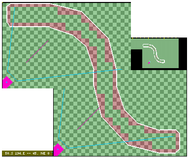
E 9 90 -- start facing east (9,90)
A 5 -- advance east to
(9,95)
R 5 -- curve to south (14,101)
A 2 -- short straight south
(17,101)
L 8 -- curve to east (25,109)
A 2 -- short straight east
(25,112)
L 0 -- cap off lane
(22,112)..
A 2
L 0
A 2 -- short straight west
(22,109)
R 5 -- curve to north (17,104)
A 2 -- short straight north
(14,104)
L 8 -- curve to west (6,96)
A 5 -- short straight west
(6,90)
L 0 -- cap off lane
(9,90)..
A 2
L 0
-- B 8 92 -- bucket track (disabled)
. -- end
of descriptor
My first try I failed to equalize the east-
and west-advances, so the resulting track didn't meet up. I also counted
wrong through the first end cap, but the error was only in the comments
and did not affect the resulting track. Here you see a stitched composite
of two screen shots.
Then I searched the console log for the "[*]"
tags of generated macro track operators -- or more particularly, for the
(unique) comments in the four curve operators, these four pairs:
R 5 -- curve to
south (14,101)
[*] '\E 10 98 (+1,+3)\S 11 100
(+1,+2)\S 14 101 (+3,+1)'
L 8 -- curve to east (25,109)
[*] '\S 20 102 (+4,+1)\E 24
105 (+4,+3)\E 25 109 (+1,+4)'
R 5 -- curve to north (17,104)
[*] '\W 21 107 (-1,-3)\N 20
105 (-1,-2)\N 17 104 (-3,-1)'
L 8 -- curve to west (6,96)
[*] '\N 11 103 (-4,-1)\W 7 100
(-4,-3)\W 6 96 (-1,-4)'
One of the reasons for using a diagonal to
merge the two curves is to shorten the vertical transit, because (unlike
the atrium at the west end of the hall) the slightly wider space at the
end of the corridor was not wide enough for a full right+left curve inside
the return lane turns. Here you see that the 90-degree curve back to the
east ends on grid row 25, but the south wall at that end is on grid row
22.
So the plan is to preserve the first segment of
the "R 5 curve to south" and join it to the final segment of the
"L 8 curve to east" with a single diagonal segment, essentially
preserving the middle segment of the curve east, which now starts after
that first segment of the curve south, at coordinate (10,98). Ordinarily
an S-curve (one left + one right) adds +14 grid units in each direction,
but by eliminating the two inner end segments, I can take "+3 +4"
= +7 off that, so that instead of ending on grid row 25, it can end
on grid row 18. I preserved the +2 advance between the two curves, for
a net reduction -5, to end on grid row 20. I preserved the horizontal advances.
So my new gentler S-curve starts with "E 10
98" as before, then ends with the "E 24 105 \E 25 109"
from the other curve, but with the southern advance reduced -5, thus:
E 10 98 -- 1st segment of R 5 curve
to south (+1,+3)
E 19 105 -- 2nd seg't merged w/2nd seg of..
(+7,+7)
E 20 109 -- 3rd segment of L 8 curve to east
(+1,+4)
I then did the same thing on the return. It
came out pretty good. I think I made a few mistakes along the way, but
looking at each iteration in the close-up map enabled me to see my mistakes.
With a little creativity like this, you can construct arbitrarily complex
tracks to run your car through.
The car we were using could turn sharper than
a 2m (actual) radius, but if the track had any curves tighter than that,
the car ran off. So mostly our test tracks were made with a tape measure,
one end anchored at the center of the curve, and the 6' mark at the other
end drawn around the circle for the outside edge tape; the inside tape
(lane width) was about 20" (52" from the center in the curves), which worked
reasonably well. Most of the tracks in this file have those dimensions.
TrakSim now supports any (integer) radius up to 16 grid units (32 park
meters = 12 feet on the floor at 1:8 scale).
PSU Stairwell
In the end, it turned out the concrete floor was
too polished for the car to see the taped track edges, and we found another
venue in the basement of the same building with carpet on the floor. The
engineering building has an open stairwell for the entire height of the
building -- I understand they use some of that open space for testing the
mechanics of falling objects -- and the floor around the base of the stairs
is a carpeted lounge with tables and chairs. We taped up a sort of oval
on the floor around the stairs, approximately like this:
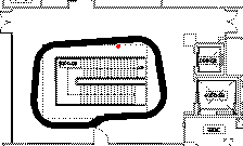
The kink on the south side was intentional, so
that the car would have at least one left curve. We had an in-scale stop
sign placed next to the eastbound part of the track as shown. After the
fact I prepared a test track specification more or less to match, partly
to verify the new track pebbling and luminance
specifications, which I left in the revised "TrackImg.txt" file
in the current distribution.
At first I tried a rather brutal near-black +
mid-gray pebble texture, then moderated it somewhat by adding another level
of gray between them, which I believe more closely resembles the actual
carpet. I left both in the file, but the second one overrides the first.
The overhead light in the lower left corner is probably brighter in effect
than the actual lamp in that lounge area, but you can use it to exercise
your track following ability in near-washed-out floor luminance, which
is probably the worst case. In real life the higher brightness normally
gets irised down by the camera's gain control, so it's not so difficult
(except under stiff gradients).
"Brussels" Track
The group got invited to show their efforts at a
conference somewhere in Europe. It was a bit of an afterthought, so the
space we have to lay out a track is an odd shape, roughly the area outlined
in the photo, and labelled "Robot Cars" in blue on the diagram. The horizontal
aisle isn't quite wide enough for our car to turn around -- I guess the
kids could do a K-turn, but probably not in time for the show, so I assumed
some of the unlabelled blue region with catering islands could be used.
The photo seems to be some other show, they have cars where the diagram
shows "Catering."  For scale, we were told the exhibitor booths are 2x3m (there are two near
the corner, but we don't know for sure the diagram is to scale), which
makes the large rectangular block on the left to be about 5x7m and the
horizontal aisle to be about 2x18m, large enough for a lane each way, but
not to turn around.
For scale, we were told the exhibitor booths are 2x3m (there are two near
the corner, but we don't know for sure the diagram is to scale), which
makes the large rectangular block on the left to be about 5x7m and the
horizontal aisle to be about 2x18m, large enough for a lane each way, but
not to turn around.
Apparently my directions for making tracks were
less than perspicuous (or else it's just plain too hard for their young
minds, I don't know which) so I did up a track myself. Here is a screen
shot of what I came up with, which is now included in the
TrackImg.txt
file labelled "BruxEst".
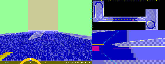
I left in the crossroads from the Figure8 track,
so you can add your own stop signs or traffic lights. I made most of the
horizontal segment into a 2-lane road with dashed line, so the cars can
pass (if so programmed). I used the standard bucket tool to fill the track,
but the Java environment I was using quit on stack overflow, so I inserted
a rectangle of track fill about in the middle to cut it in half, which
worked. Due to space considerations, the northbound segment of the crossroad
is already into its curve, so I did some of the intersection by hand. It's
a little clumsy, but presumably the kids will tape up the blue carpet at
the show nicely, and that's all the visitors will see. I also brightened
up the track at the left Y to match the photograph illumination, and a
little at the other end of the aisle although it's less obvious in the
photo. This track specification allowed the participants to tune some of
their driving parameters before they got to Europe.
It turned out that they were able to tighten up
the curves which made spilling out into the Catering area unnecessary (and
after we arrived, obviously inadvisable), so I replaced it with a new track
descriptor closer to my recollection of the actual track, which now uses
the new improved curve macros to get the required tighter turns. The original
"Brussels" track has now been moved later in the file and relabelled "BruxEst".
The "Brussels" track in the current distribution file vigorously exercises
partial curves of varying radii.

Getting the curves to line up properly proved
rather tricky in the "wavy" area along the nominal eastbound side of the
track -- it turned out after we arrived, that what I supposed was north
is actually south, but it doesn't really matter if the directions are all
backwards, so long as you are consistent -- so I set the car position to
face the region I was working in, then made a guess at a suitable curve
segment, then rebuilt the track and looked at what it did. I iterated this
over a couple days to get the track you see in the file, and even so, it's
still a bit lumpy. You might find it simpler to just create your own curves
one segment at a time using compass operators (I did that a couple of times
in this track).
I tested this new track with the StayInTrack
and FixedSpeed modes turned
on, and the car ran off the track at the apex of the loop on the right
past the crossover where the curve is tightest; the actual car in Brussels
stayed on the track running all day long. Of course they were using their
own steering code. Just remember, TrakSim is only an approximation for
getting you going. The final proof of your code is in the real car on the
real floor or track.
Back to front of TrakSim
Rev. 2019 July 4